Power Supply
Contents
Power Supply
Power Supply is an important internal part of any laptop and in our case we are trying to redesign it a bit to be more efficient and also try to add stable current "comb" that will comply to all ACPI requirements.
Balthazar PSU
Based on the above, these are the outlines:
1. Universal power adapter – 12Vdc/5A (60VA max) – the most usual laptop power connector / either exterior or inserted into chasis skeleton 2. Input RFI filter 3. Buck/ boost converter - 5-15V -> 5.1V (which is VSYS voltage on mainboard) 4. LiPo battery pack single cell charger -> from SYS voltage 5.1V 5. Large LiPo battery pack (10000mAh) – single cells / in parallel = 3.6V – three terminal connector (-Vbat=gnd, thermistor NTC_TS, +Vbat=3.6V) 6. Options: charge to/from/use external 5V battery pack (Usb-A and/or Usb-C connectors), solar panel charger, ... 7. VSYS voltage is the main motherboard voltage line – use appropriate buck or boost converters on all separate functional modules (cpu, graphics, ram, etc.)
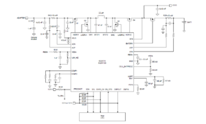
Texas Instruments BQ25713 Battery Charger
-> http://www.ti.com/lit/ds/symlink/bq25713.pdf
Texas Instruments BQ27Z561 Battery Fuel Gauge -> http://www.ti.com/lit/ds/symlink/bq27z561.pdf
Optional: Texas Instruments BQ24210 Solar Panel Charger
The valid adapter range is from 3.5 V (VVBUS_CONVEN) to 24 V (ACOV) with at least 500-mA current rating. When CHRG_OK goes HIGH, the system is powered from adapter through the charger. When adapter is removed, the system is connected to battery through BATFET. Typically the battery depletion threshold should be greater than the minimum system voltage so that the battery capacity can be fully utilized for maximum battery life (meaning: rather use 2S battery pack).Four external N-channel MOSFETs are used for a synchronous switching battery charger. The gate drivers are internally integrated into the IC with 6 V of gate drive voltage. 30 V or higher voltage rating MOSFETs are preferred for 19 V - 20 V input voltage.
Input Capacitor
Input capacitor should have enough ripple current rating to absorb input switching ripple current. The worst case RMS ripple current is half of the charging current when duty cycle is 0.5 in buck mode. If the converter does not operate at 50% duty cycle, then the worst case capacitor RMS current occurs where the duty cycle is closest to 50%. Low ESR ceramic capacitor such as X7R or X5R is preferred for input decoupling capacitor and should be placed to the drain of the high side MOSFET and source of the low side MOSFET as close as possible. Voltage rating of the capacitor must be higher than normal input voltage level. 25 V rating or higher capacitor is preferred for 19 V - 20 V input voltage. Minimum 4 - 6 pcs of 10-μF 0805 size capacitor is suggested for 45 - 65 W adapter design.
Output Capacitor
To get good loop stability, the resonant frequency of the output inductor and output capacitor should be designed between 10 kHz and 20 kHz. The preferred ceramic capacitor is 25-V X7R or X5R for output capacitor. Minimum 6 pcs of 10-μF 0805 size capacitor is suggested to be placed by the inductor. Place the capacitors after Q4 drain. Place minimum 10 μF after the charge current sense resistor for best stability.
Schematics
Other options
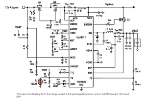
BQ24171 related - 4.5V to 17V input operating voltage. Much cheaper than BQ25713 – available individually. There are several methods to damping or limiting the overvoltage spike during adapter hot plug-in. An electrolytic capacitor with high ESR as an input capacitor can damp the overvoltage spike well below the IC maximum pin voltage rating. A high current capability TVS Zener diode can also limit the overvoltage level to an IC safe level.
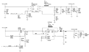
VSYS Buck/ boost dc/dc converters
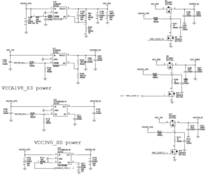
Reference to a Pinebook Pro:
Buck/ boost dc/dc converters (these are on the mainboard) This is solution by pinebookpro v2.1 (uses RK3399 SOC – powered by 1.8V)
New PCB module for Balthazar has been developed.
Power supply unit based on battery charger (Texas Instruments) chip from any available source (12V / 4A mains adapter or USB power bank) and two separate buck/ boost converters for 3.3V or 5V for the necessary computer blocks (the LCD and the processor board). The board also has a stereo D-class audio power amplifier powered directly from battery (and/or adapter) 3.6 to 4.2V - so as not to dwell on the two much more important stabilised sources.
Details on PSU module
Features:
   • LiIo / LiPo battery charger 3A with wide range of input options
   • mains adapter 4.9-17V/3A, USB power bank 5V power sources
   • two independent dc-dc buck/ boost converters (each 3.3V/4A or 5V/3A)
   • options for USB on-the-go power supply for external devices
   • options for logic control of charger
   • manual charge enable/ disable switch
   • class D stereo audio power amplifier 2 x 3W
   • manual audio mute switch
Bathazar PSU schematic in:
Bill of materials (BoM) in:
PCB ready for prototype as KiCad files are available at our Github pages.
Those will be regularly updated as schematics and PCBs are continuously improved and optimised.


